March 26, 2026 · 7 min read
Site & Clearances (Items 1 - 5)
Get these five right on the drawings and half the install headaches disappear.
- 1. Dedicated room, not a shared closet - keeps noise, heat, and vibration off other equipment.
- 2. Minimum 3 ft service clearance on the access side of every machine, 2 ft everywhere else.
- 3. Slab thick enough for machine weight and vibration - check the compressor manual, not a guess.
- 4. Door wide enough to roll the largest piece of equipment in and out (usually the receiver tank).
- 5. Not directly below offices, meeting rooms, or dust-producing operations.
Ventilation & Heat Rejection (Items 6 - 10)
A rotary screw compressor rejects roughly 2,545 BTU per hour per HP as heat. A 50 HP compressor puts about 125,000 BTU/hr into the room. Without ventilation, the room bakes and the compressor trips on high temperature.
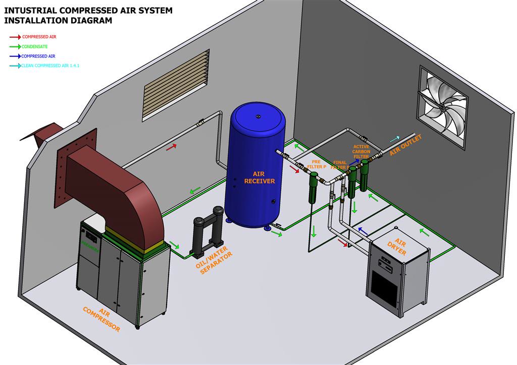
- 6. Intake louver on one wall, exhaust fan on the opposite wall - not the same wall.
- 7. Exhaust fan sized to move the compressor heat plus 25 percent margin.
- 8. Louvers protected from rain, snow, and bird intrusion but not restricted.
- 9. Intake air free of dust, oil mist, paint fumes, and welding smoke.
- 10. Ambient temperature stays under 105 F at the compressor intake, year-round.
Electrical & Controls (Items 11 - 14)
Electrical scope is where install schedules slip. Coordinate with your electrician before the compressor arrives.
- 11. Disconnect within sight of each piece of equipment (compressor, dryer).
- 12. Wire sized for full-load amps plus code margin, not brochure HP.
- 13. Dedicated circuit for the dryer - never a shared feed.
- 14. Room in the panel for a future compressor or VFD upgrade.
Building a new shop? Send drawings early - a 30-minute review saves rework.
Get a room design reviewStartup, Documentation & PM (Items 15 - 18)
The last four items separate a compressor drop-off from a real install.
- 15. Floor drain with oil-water separator sized for total condensate load.
- 16. Zero-loss electronic drains on each condensate point, routed to the separator.
- 17. Documented commissioning: verified rotation, load-test amp draw, dryer dew point, filter pressure drops recorded on paper.
- 18. PM schedule handed off with drawings, spare parts list, and a service partner named before the truck leaves.